my aim for this project was to create a performable effect to work in tandem with an acoustic piano. i originally had 3 sub-goals:
- putting together an effects processing patch in puredata.
- deciding how i'd like to interface with the patch.
- figuring out how to most easily mic up the piano, and make the whole system convenient for performance.
my background is in piano performance, and since becoming interested in electronic music, i've been curious as to how i can integrate the skills i already have with the ones i'm currently developing. prior to starting this project, i hadn't seriously attempted to bridge my interests in these two areas. i found that in bringing electronics to the piano, or vice versa, i had difficulty retaining the artistic freedom i felt when creating with either tool separately. this motivated me to create an effect and interface that are performable both on their own and with the piano.
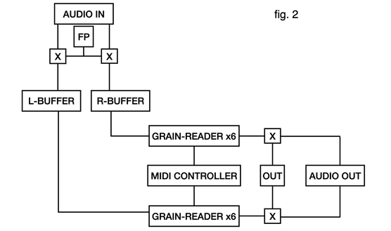
the overall signal flow of the patch is as follows:
- audio, from a live input or a loaded sample, is sent to 2 circular buffers. when recording is activated, this audio is written into the buffers. a midi foot pedal controls whether or not recording is active. the recordhead slider denotes the position in the buffer at which audio will be written. the clear button clears the contents of both buffers.
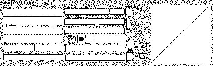
- there are 6 pairs of grain-readers (one for the left buffer, one for the right) that read audio from the buffers. each of these pairs has a dedicated playback speed, transposition, and volume control (as seen in figure 1). fine tune offers finer transposition control. the radio object labeled loop # sets which grain-pair is being controlled.
- while each of these parameters can be set for each grain-pair individually, there are also global grain controls, labeled speed and density. density controls the chance that any given grains parameters will be randomized, and speed controls the rate of randomization. these controls affect the left and right portion of each grain-pair individually. the phase-lock button sets the overall position of each grain to the beginning of the buffer, and sets the playback speed of each grain to normal, syncing all the grains together in time with one another.
- finally, volume at the output is controlled by the output slider. i've assigned various midi controls on my midi controller to each of the available parameters.
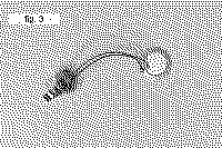
I decided to use piezo contact mics to mic the piano. While the audio quality isn't great, using contact microphones eliminates any risk of feedback while recording, and the low fidelity of the piezos adds some charm to the sound.
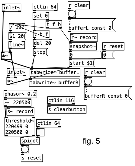
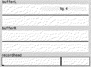
When recording is initiated, incoming audio is recorded into the buffers. The recordhead slider displays the portion of the buffers that is overwritten while recording is enabled. When recording is initiated, writing begins, and the amplitude of the incoming audio is enveloped from 0 to 1. When recording is ended, the audio is enveloped from 1 to 0, and writing stops. This is done to prevent any sudden jumps in amplitude. If the end of a buffer is reached while recording, then the record-head circles back to the beginning of the buffer.
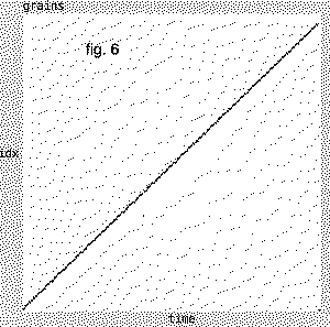
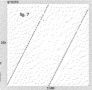
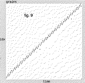
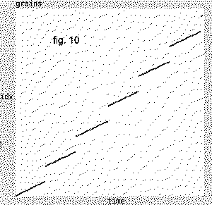
Figure 6 illustrates the relationship between sample index and time when a buffer is played back at normal speed and normal pitch. One way to play the buffer at twice the pitch would be to play the buffer at twice the speed, however a change in playback speed may not be desired (fig. 7). Borrowing a technique from granular synthesis, we can separate playback speed and playback pitch.
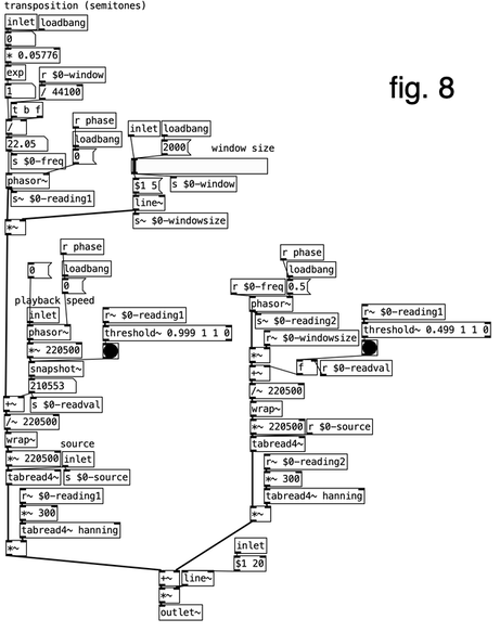
Each grain-reader reads through its corresponding buffer according to the sum of two sawtooth waves (called phasor~ in Pd). The first sawtooth determines playback pitch, the second determines playback speed. The pitch phasor reads through a small window of the buffer at a frequency corresponding to the desired pitch. The size of this window is determined by the window size slider in figure 8. For the purposes of my patch, I've decided to keep it at 2000 samples. At the beginning of each cycle, this smaller phasor is added to an offset value determined by the playback speed phasor. This offset compensates for any unwanted speed changes by overlapping windows, and repeating portions of the buffer (fig. 9), or skipping portions of the buffer (fig. 10). The sum of these sawtooth waves is sent to a tabread4~ object, which reads through the corresponding buffer. The sudden jumps in sample index cause a click at the beginning of each new window, so the amplitude of the output is scaled by a hanning function. This windowing is done with 50% overlap to maintain constant power.
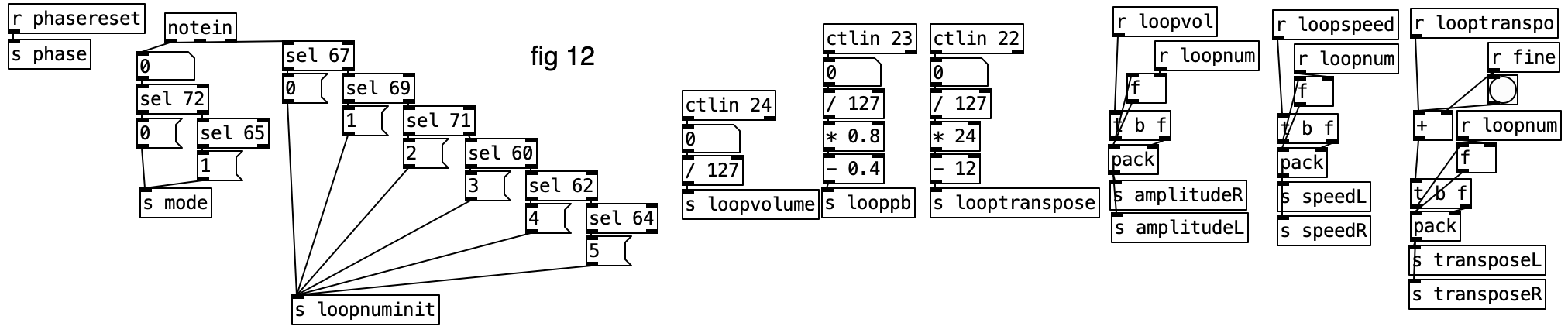
There are micro and macro controls for the patch. The micro controls are relatively straight-forward, and change the parameters of each individual grain-pair. Using the loop # radio object (fig. 1), or the corresponding midi control, one can select which grain-pair is being affected. When any given micro control change is given, the value from that slider is prepended by a number (0-5) before being sent to the cloned grain-reader patch (fig. 6). The sub-patch above (fig. 12) shows how this is done, and how the midi controls are mapped.
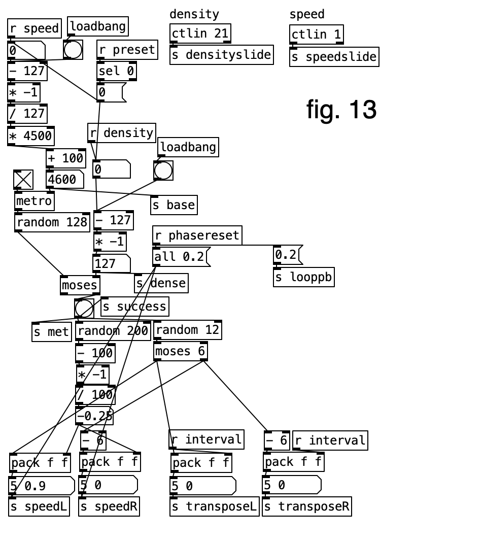
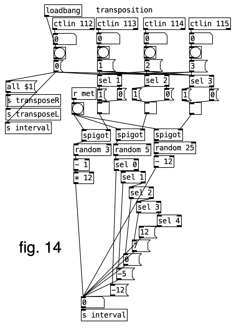
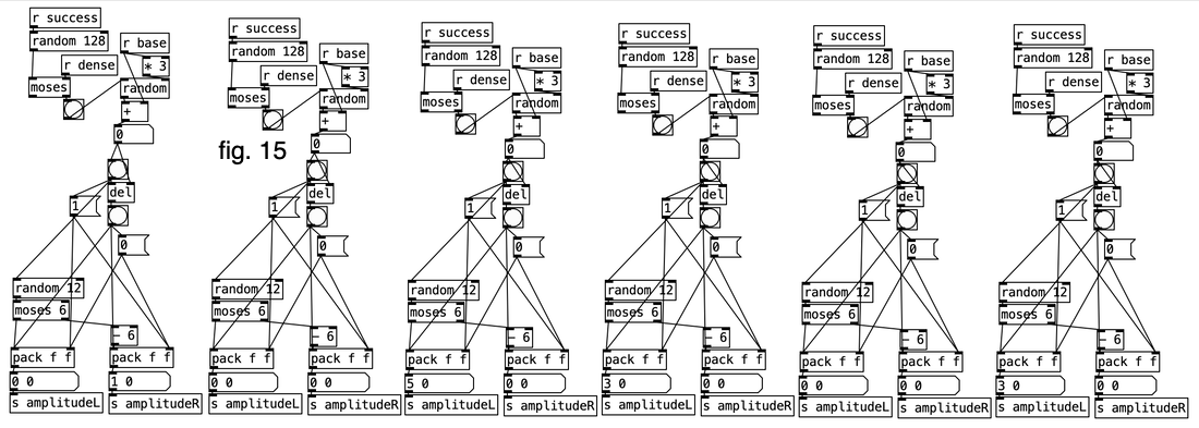
The macro controls are a bit more convoluted. (fig. 13, 14, 15 below) The two macro controls are labeled speed and density. They function together to randomize the parameters of each grain. Speed controls the rate of a metro~which bangs a random object. The outputted value is compared to a value determined by the density control, using the moses~ object. If density is low, then the probability that parameter randomization will occur is low. Figure 13 illustrates this process. If the random value passes the moses object, then one of the grains has its playback speed and pitch randomized. A random transposition value is chosen from a set determined in figure 14. There are four sets; no transposition, octave up or down, 5th up or 4th down, or any semitone within an octave from the original pitch. The active set can be selected by the user. In addition, a bang is sent to each of the random objects in figure 15, the output of which goes through another comparison against the density value. If this random value passes the test, then one of the grains is sent an amplitude envelope with a randomized duration.
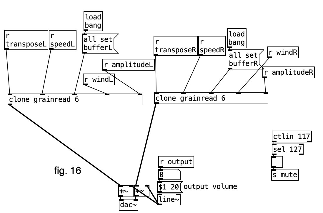
The audio output stage of the patch can be seen in figure 16. The objects labeled clone grain read are clones of the grain-reader patch (fig. 6). As stated earlier, all of the parameter changes sent to the clone objects are prepended by a clone number that addresses the parameter change to the correct clone. There are 6 clones that read from the left buffer, and 6 clones that read from the right buffer. The combined output of either side is scaled by the output slider (fig. 1). There is also a mute button in figure 1, which mutes the output.
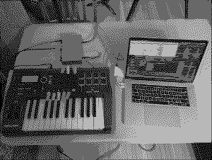
While I do feel that I accomplished most of what I set out to do, my original goals for this project were ambitious, and there are some things that I left out/didn't get to. I spent most of my time working on on the patch portion of the project, as it underwent a few different iterations. This left me little time to further develop the physical interface portion of the project, and I ended up using a MIDI controller that I already had to control the patch. While it works as intended, I would like to further explore interface design in the future.